Monday, June 15, 2015

Stepper-driven paste extruder for Delta printers

Status: in progress

Last summer, one of my tinkering buddies, Miranda, and I built an FDM-type 3D printer that extruded chocolate instead of plastic.  We drew heavily from the work of Jonathan Keep, who had previously been working on extruding other paste materials but took a side-trip into chocolate.  Actually, it would be more fair to say that we used his process as a baseline to work from; aside from some custom 3D printed parts in the extruder and the fact that we used a different delta design, we essentially replicated his experiment.

Photo courtesy of Dover Mini Maker Faire
We learned a lot in the process, and had discussed evolving the extruder to be more accurate.  Air pressure was functional but had the downside of being difficult to stop and start rapidly without adding in additional valving (and potentially controls for said valves) to blow off the pressure in the system.  Looking at other designs, like the Universal Paste Extruder, the Frostruder, and the Claystruder, I saw some limitations for our particular application and I wanted to try and address them directly.  Admittedly, we might have chosen an easier medium - notably, one that didn't require precise temperature control - to start with.

In our case, I wanted to keep weight on the effector as low as possible - that could mean forcing material over a tube, but in the case of chocolate, that would require keeping the whole tube heated, which is possible but complicated.  Keeping the material reservoir on the head was possible, but bringing the weight of the stepper motor along with it (as is the case with several other designs) was not a compromise I wanted to make.  We then discussed driving the mechanism removely using a flexible drive shaft like a speedometer cable, which might also offset some of the effector weight since the cable is a bit springy.

That lead to some sketches:

Discussions, test fittings, revisions, additions from other Makerspace members resulted in this:


The stepper drives the Dremel flex shaft adapter which turns the screw, driving it downward, and pushing the plunger which extrudes the material in the syringe.

The upper backplate/cable support, the syringe holder, and the plunger are 3D printed.  The mechanism is made using 6mm linear shafting and bearings (which just snap in, thanks for that idea Paul), a section of 1/4" ACME threaded rod and captive nut, and miscellaneous hardware.  No coupler was needed to mate the Dremel tool holder to the ACME rod, but I did need to turn it down to 1/8" diameter in the lathe.  The coupler from the stepper motor to the other end of the flexible shaft had to be machined from scratch.


The pivot between the screw drive and the plunger isn't properly centered, leading to an unfortunate amount of friction, and the Dremel flexible shaft drive is a little more springy than it seemed at first, but aside from that, it appears to be viable.  Hopefully we'll be able to do some test runs soon.

8/30/2015 update:
The parts to construct this extruder are now available on Thingiverse [link] and a video of the printer in action is available on Youtube [link].

Monday, April 27, 2015

Ball joint for aluminum extrusions

In the course of designing a humanoid sculpture for an upcoming exhibit at the Dover Children’s Museum, I decided to try and come up with a lockable ball joint using common hardware.

I’ll get into the overall design of the sculpture in another post, but I’d already decided to build the skeleton out of aluminum extrusions; I sort of have a ’thing’ for them.  They’re cheap and versatile, strong, and look cool.  I had imagined using a through-bolted ball on the shoulder and using two smaller “stubs” of extrusion with milled pockets to hold the ball captive and exert clamping force.  When I was prepping some of the pieces, I had a better idea.

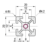
The extrusion I’d used previously was 20mm square with a simple one-hole cross section:
But in this project, I was using 30mm square extrusion and it has a very different cross-section:
Those 4 perimeter holes are sized to be tapped for M5 thread, which gave me an idea.  If I drilled 4 matching holes in an appropriately-sized retaining plate, I could use that to retain the ball.  I got a .75” ID, 2.0” OD flat washer and drilled it up in the mill.  I tapped the extrusion holes and bolted it together.  The result is below.


The amount of grip the washer exerts on the ball is significant, and adjusting it is just a matter of loosening the bolts slightly, repositioning the ball, and cinching them back up. I’ve built them with both steel and delrin balls.  Steel looks cooler and is available predrilled/tapped, which I recommend if you want metal because most balls available in this size are hardened steel bearing balls and are difficult to machine.  Delrin is cheap ($10 for qty. 10 1” balls) and provides better grip.

I sourced the extrusions from Misumi.  The steel and delrin balls came from McMaster.

I plan to use these a lot.